Typical Structure and Working Principle of A Permanent Magnet Generator
Introduction
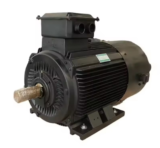
A permanent magnet alternator (also called PMA, permanent magnet generator, PMG or magneto) relies on the magnetic field generated by a permanent magnet to convert mechanical energy into electrical power. It can generate AC current, with which it can power the whole engine and charge the battery. In this article, we will focus on the typical structure of a permanent magnet generator and also give a brief introduction to its working principle.

Structure of a Permanent Magnet Generator
A modern permanent magnet generator contains both moving and stationary coils of wire. In the generator, however, the moving coil, called the rotor, uses current supplied through slip rings to generate a moving field. Power is extracted from the stationary field coils.

- The stator contains six coils of copper wire cast in fiberglass resin. It is mounted onto the spine and does not move.
- The magnet rotors are mounted on bearings turning on the shaft. There're two rotors: the rear one behind the stator and the front one on the outside, which are connected by the long studs passing through a hole in the stator.
- The blades are mounted on the same studs. They will drive the magnet rotors to rotate and move through the coils. During this process, electric power is produced.
- Shaft: The rotor is mounted on a central shaft, which is connected to the prime mover (e.g., a turbine or engine) that drives the rotation of the rotor.
- Bearings: Bearings support the shaft and allow it to rotate smoothly, reducing friction and wear on the generator components.
- Housing: The entire assembly is enclosed in a protective housing that shields the internal components from environmental factors like dust, moisture, and mechanical damage.
Related reading: Permanent Magnet Generator: An Overview
Working Principle of a Permanent Magnet Generator
The working principle of a Permanent Magnet Generator is based on Faraday's Law of Electromagnetic Induction, which states that a change in magnetic flux through a coil will induce an electromotive force (EMF) in the coil.
- Magnetic Field Creation: As the prime mover rotates the shaft, the rotor spins, causing the permanent magnets attached to the rotor to move past the stator coils. These magnets create a strong and stable magnetic field.
- Induction of Electromotive Force (EMF): As the rotor (with its attached permanent magnets) spins, the magnetic field lines cut across the stationary stator coils. According to Faraday's Law, this movement induces an electromotive force (EMF) in the coils.
- Generation of Electricity: The induced EMF causes a current to flow through the stator coils, generating electricity. The amount of electricity generated depends on factors such as the speed of the rotor, the strength of the magnetic field, and the number of turns in the stator coils.
- Output: The generated AC (alternating current) electricity is then collected from the stator coils and can be used directly, converted to DC (direct current), or conditioned for specific applications.
Applications of Permanent Magnet Generators
Permanent Magnet Generators are widely used in various applications, including:
- Wind Turbines: PMGs are commonly used in wind turbines due to their efficiency and reliability.
- Portable Generators: Their compact size and low maintenance make them ideal for portable power generation.
- Marine and Aerospace: PMGs are used in marine and aerospace applications where reliability and weight are crucial.
Conclusion
In summary, the structure and working principle of Permanent Magnet Generators make them a highly efficient and versatile choice for generating electricity. Their ability to reliably convert mechanical energy into electrical power, coupled with their compact design and low maintenance requirements, make PMGs ideal for a variety of applications. Their widespread use underscores their importance in modern power generation solutions. For more information, please check Stanford Magnets.


